Showing posts with label Sensors. Show all posts

OpenNI: Kinect and more!

OpenNI has come to public attention lately because it is used as a free programming tool for popular XBox 3D sensor Kinect; however, it offers much more.


OpenNI (Open Natural Interaction) is a multi-language, cross-platform framework that defines
APIs for writing applications utilizing Natural Interaction. OpenNI APIs are composed of a set of
interfaces for writing NI applications based on:

- Vision and audio sensors (the devices that ‘see’ and ‘hear’ the figures and their
surroundings.)
- Vision and audio perception middleware (the software components that analyze the audio
and visual data that is recorded from the scene, and comprehend it).


In brief, OpenNi provides a HAL (Hardware Abstraction Layer) for a 3D sensor, RGB camera,
IR camera and audio device (not surprisingly integrated in Kinect) and middleware to avoid programming basic functions like body detection and analysis (joints, orientation, center of mass ...), hand point detection and analysis, gesture recognition or basic scene analysis (e.g. separation between the foreground and background, coordinates of the floor plane, individual identification of figures ...). This is really convenient if we think that alternatives previous to Kinect to this respect involved 9000 EUR TOF (Time of Flight) cameras or less reliable and much more computationally expensive stereo systems and we had to program stuff on our own.

OpenNI follows a philosophy similar to ROS: devices and program modules are modeled as nodes that interact with each other, conforming the so-called production chains.

The main advantage of OpenNI is that it is currently being integrated in every robotics open framework, so we can use Kinect in any application we have developed (and we are!)

Make your own assistive wheelchair in 11 easy steps


All the assembly information you'll need to turn your power wheelchair into a robot and survive the process is gathered in this technical annex Really! :D

Outdoors Hokuyo laser, anyone?


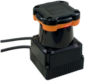
HOKUYO UTM-30LX: I saw this Hokuyo model during ICRA'10 and it seemed to work pretty well in the expo section. They promised me at the stand that it would work well in outdoor conditions despite light changes and noise. It costs twice what your regular Hokuyo would, but it is much cheaper and easier to use than stereoscopy or single-camera disparity range calculation. Might be worth a try!
  • 25ms per scan
  • Low power comsumption 8.4W
  • Power source 12Vdc @700ma
  • High accuracy ± 30mm
  • 240° Scanning area
  • High resolution 0.25°
  • Compact W:60, D:60, H87mm
  • Light weight 370g
  • USB 2.0 (Full Speed)
  • Range: 20 to 30,000mm

The X marks the spot

The easiest solution to the localization problem is to use dead reckoning: if we know how fast and how long we have been moving, we can estimate approximately how far we are from our original position. Alternatively, we can measure the number and length of our steps or the number of wheel turns of our vehicle to do the same. Indeed, boats used to proceed like that: their speed and direction was estimated in terms of how long a knot in a rope dropped from the bow of the vessel took to reach its back side (1) and new locations were estimated in terms of how long that speed was kept. Naturally, odometrics can only work for a time, because errors tend to accumulate in an unbounded way. If no external reference is used to correct the position from time to time, after a while the vehicle is lost. One could try, for example, to precalculate the path to a spot 10 m away and then try to walk there blindfolded. Chances are one would most likely end fairly far from the desired destination, specially if turns are involved, or, at worst, stuck into an unexpected obstacle. In order to avoid this problem, we could just open the eyes that, in the robot case, means we can combine different information sources using methods like Kalman filters or Montecarlo techniques to remove or, at least, reduce uncertainty.


Ok, so maybe dead reckoning was not such a good idea...
Things are easier if we know the location of at least two relevant features in the environment that we can perceive at a given location. For example, boats originally relied on the position of the stars and nowadays they use GPS satellites to triangulate where they are. Mobile robots can do the same if external beacons are available (GPS, ultrasounds, wireless beacons, etc).

Of course, active beacons might not be available; GPS, for example, can not be used indoors. If this is the case, robots can refer to known features in the environment -natural or artificial landmarks- to estimate where they are, in the same way we could check a metro station we are watching in a map to decide where we are at the moment. In these cases, cameras are typically used not as range sensors, but to detect the expected landmarks within the field of view e.g. (Urdiales et al, 2009).
A very special case among these ones is omnicameras, whose optics have been designed so that all points in the world are projected through a single center of projection. Hence, they capture 360º fields of view in a single frame and usually extract fairly reliable landmarks from the picture (see Keith Price bibliography on the subject).

If cameras are not available or do not want to be used, geometric landmarks can also be detected. These landmarks are significant, distinct locations that can be detected by means of range sensors, like a corridor with two open doors at each side. This would be equivalent to try to check where we are by touching the walls if the lights go out. However, similar landmarks may exist in different areas of the environment, so it is necessary to disambiguate perceptions by keeping some track of the mobile position on accumulating several landmarks in a row via a statistic method like, say, Markov Model e.g. (Baltzakis, 2003)(Fox, 1998).

In absence of a model of the environment, it is necessary to correct the position, store detected landmarks and build a new model, all at the same time. Think, for example, of trying to draw a map of a city we have never been in by marking every distinctive building we see and trying to guess the distance and relative position between each two of them. This problem is known as SLAM. SLAM conforms a quite complex, complete field of research and it is out of the scope of our work.


(1) In fact, the idea was to sing a song and write down in the bitacora in which word it had stopped. One can only hope that the crew was able to keep the rythm.

Sense and sensibility

Stereo perception of distance
Traditionally, wheelchairs relied on range sensors to navigate. These sensors -in decreasing order of cost, weight and range- include laser, sonar, infrared and bumpers, although cameras have been also used to measure distance either in pairs (stereovision/divergence) or via optical flow.

TOF sensor fusion

Most range sensors basically use the TOF (Time of Flight) of an echo signal to offer their distance to the closest obstacle in the direction of the sensor, but many of these can be rotated like a sonar in a submarine to cover a wider range of detection. Others, like cameras, provide information on a wider area, but this information is typically more complex to process. In a dynamic, potentially unstructured environment, a quick response time might be the difference between safety and collision, so in many cases, when video cameras are used, they are combined with other range sensors to achieve faster responses. Furthermore, visual information is so rich that video processing has only been solved when some constraints can be applied. These restrictions usually imply some knowledge about the operation environment and a heavy specific problem-solving orientation. Simpler range sensors also present their own drawbacks. Sonar sensors, for example, have an uncertainty angle that, in models like Polaroid, may be up to 22.5º. Consequently, when obstacles are at a significant distance, say 4-5 m, we know how far they are, but not exactly where. Infrarred sensors are sensitive to natural light and their output may change sharply when there is a significant illumination change, like whenever someone is stepping in front of a window. switches on a light or opens a door. Lasers can not detect glass doors and deal poorly with black surfaces. Furthermore, all three of these sensors only detect obstacles in their own plane, so irregular objects like a table might be completely missed. Recently, though, laser sensors have become smaller, cheaper and stronger, so they have been particularly favored by the wheelchair industry. A classic SICK LMS 291-S05 laser weights 4.5kg and is 156 x 155 x 210mm, whereas a modern Hokuyo URG-04LX weights 160g and is just 50 x 50 x 70mm.

Hokuyo laser


In any case, since all sensors have advantages and drawbacks, it is usual to work with several ones or, at least, to statistically combine the readings of a single one in time and space to obtain more reliable knowledge on the environment. If these readings are combined in a short time span within the surroundings of the robot, range sensor readings can be used to avoid close obstacles by heading it in a free direction. Readings can also be combined into a wider model of the environment to predict more efficient and safer trajectories to the goal, to combine several goals or to coordinate different mobiles. In order to build global models of the environment, though, it is important to know the position of the mobile within the environment with some accuracy. Otherwise, it would be like asking directions to someone who is actually lost.

Older Posts Home

Recent News

-Biometrically adapted wheelchair control paper accepted in IEEE Trans. on NSRE :) -New paper on collaborative navigation in hospitals accepted in Autonomous Robots

Followers


Recent Comments